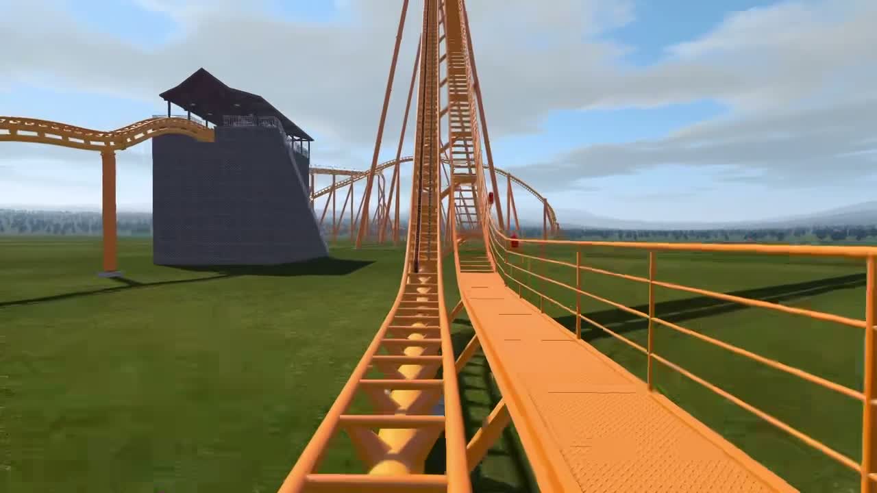
A complete ride. The decisions, geometry and load paths behind the next iteration.
Student portfolio: the ride is a NoLimits 2 simulation. The calculations below are separate worked examples with stated assumptions, not a structural assessment of that ride.
First complete ride · NoLimits 2Open the design notebook
The next design decision
Compare a layout, explain a trade-off, and record the reason for a revision.
Connect one layout decision to a documented result and explain what changed.
Project assumptions & scope
Actual model assumptions have not yet been recorded.
Student work in progress. The illustrative geometry is separate from Aiden’s model.
02
ENGINEERING / FROM EXPERIENCE TO EVIDENCE
FEEL THE RIDE. FOLLOW THE FORCE.
A ride is an experience. A structure is a load path. Here’s one small, worked example.
INTERACTIVE MECHANICS STUDYWorked example · assumed load
One force. A moment. A stress you can explain.
A horizontal force enters a fixed-base circular tube. Follow it through equilibrium, section geometry and bending stress—then change one input to test the reasoning.
Applied force 20 kNLever arm 4.0 m
Applied force Resisting shear + moment
Circular tube Ø324 mm · wall 12 mm
Schematic · not to scale. Circle shows the tube cross-section.
Model: straight, uniform tube · fixed base · static lateral tip force · 12 mm wall.
CHANGE AN ASSUMPTION
Given force · fixed base · wall 12 mm Schematic · not to scale
BASE MOMENT
80.0kN·m
BENDING STRESS DEMAND
90.4MPa
Force and lever arm create the moment. Section geometry determines the elastic bending stress.
Equilibrium: ΣFₓ = 0 → base shear 20 kN left. ΣM = 0 → base moment 80.0 kN·m counterclockwise. No vertical load is included, so axial force is zero.
The base is idealized as preventing translation and rotation. The assumed lateral tip force is perpendicular to the lever arm. The tube has a constant, concentric circular section; wall thickness stays at 12 mm. Small-displacement, linear-elastic bending is assumed. Axial load, torsion, shear stress, local effects and self-weight are omitted.
Use one unit system: 1 kN·m = 10⁶ N·mm; I is the second moment of area in mm⁴; c = D/2 is in mm. Then Mc/I has units N/mm², equal to MPa. The tube’s I is the outer circle’s value minus the inner circle’s value.
90.4 MPa is the default model’s outer-fibre bending stress magnitude at the base: tension on one side, compression on the other. It is a demand, not a capacity or a safety factor. No material grade or yield check has been supplied.
For an actual support, start with verified three-dimensional reactions and load combinations. Then check combined actions, material resistance, stability, fatigue, connections and foundations under the applicable design requirements. The slider ranges are exploration choices, not allowable limits.
Walk through the reasoning
Where did 20 kN come from? It is a stated teaching input, not a force extracted from this ride. A project calculation would need a justified support reaction.
Why multiply by 4 m? Moment equilibrium at the fixed base gives M = Fh because h is the perpendicular lever arm. The base also supplies an opposing horizontal reaction.
Why does the tube geometry matter? I describes how area is distributed about the bending axis. Removing the inner circle gives the hollow section; c locates its outer fibre.
What changes when a slider moves? Doubling force or height doubles moment and stress. Increasing diameter from 324 to 400 mm at the same 12 mm wall lowers stress from 90.4 to 58.1 MPa; the applied moment stays 80 kN·m.
What would you check next? Actual load cases and material grade, then combined stresses, stability, fatigue and the connection-to-foundation load path. A stress number alone does not establish adequacy.
NOLIMITS 2 / RIDER GEOMETRY
Same bank. Different pivot.
The heartline is an idealized rider reference used to shape track banking. Its offset depends on the coaster style and seating geometry.
For this exercise, r = 1.50 m is the assumed offset from the track centre at rail level to the rider reference. The actual offset depends on the selected coaster style.
Rider reference Track centreLooking forward · +bank left / −bank right Schematic · not to scale
CHOOSE THE PIVOT
Track-centre displacement
Sideways1.06 mright
Vertical0.44 mup
Banking about the heartline holds this idealized rider reference fixed while the rails move around it.
How the geometry works
One cross-section, one rotation
Look forward along a straight, level track: positive bank is left. Start with track centre C = (0, 0) and rider reference H = (0, r). With positive bank θ, rotating about C gives H = (−r sin θ, r cos θ). Rotating about H keeps H fixed and gives C = (r sin θ, r − r cos θ).
At r = 1.50 m and θ = 45°, the moving point shifts 1.06 m sideways and 0.44 m vertically. The track-to-reference distance stays r in both modes.
Confirm the actual project setting
NoLimits recommends “Heartline of the current style” under Coaster Properties → Mode → Spline Position. Confirm Aiden’s selected style and offset before documenting his model.
The 0.50–2.00 m offset and −60° to +60° bank ranges are for exploration, not allowable limits. Geometry only: no speeds, accelerations or loads are calculated.
Catalog references frame the questions a project study needs to answer. They do not represent a completed ASTM review or a compliance finding.
Open the project’s reference & evidence register
F2291-26A is listed as active in ASTM’s public catalog, checked October 15, 2026. F2291-26 is a historical reference edition. Full clauses and applicability need authorized standard access and qualified review.
Project standards evidence register
Reference / edition
Study topic
Evidence
Assumptions & review
Open Aiden’s project engineering & exported data
Project engineering question
Connect exported ride data with civil-engineering questions.
A focused study from Aiden’s actual design will be documented separately from the website example.
Ride data
No sourced ride-data export has been added yet.
Inspect the supplied data
Time
Vertical
Lateral
Peak g alone does not establish a pass or fail. Source, axes, duration and interpretation matter.